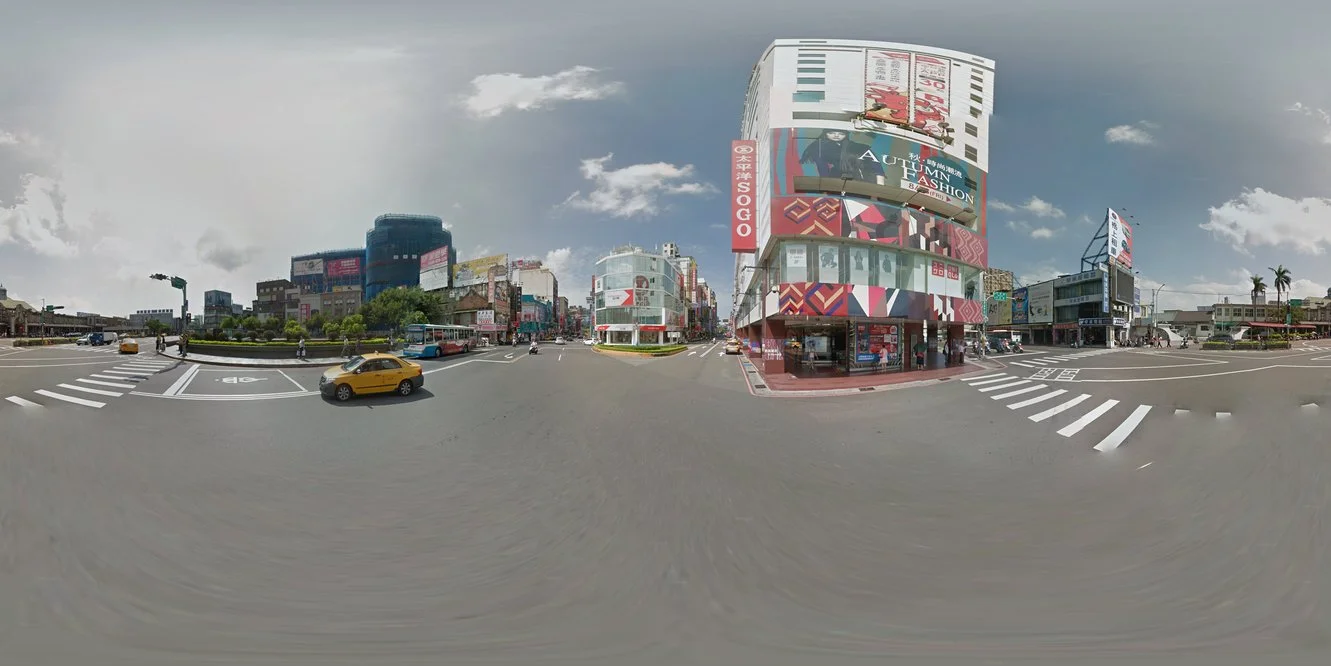
Recently I had a task to convert between perspective and equirectangular projections. Equirectangular projections can be found in VR and 360 degree image/video content. Although there are more efficient projection available today for 360 media content[1], equirectangular remains the simplest and a widely supported format. In any case, it is a good first projection to understand before moving onto the more sophisticated ones.
Perspective Projection
Perpsective projections are what you get when you take a photo of your camera. Objects that are further away from the camera appear smaller and all the lines appear to project toward vanishing points (i.e. where the parallel lines seem to converge).
Recall that the Pinhole Camera model (bet used for a perspective projection), where some real-world point with coordinates is projected onto the image plane at as
Where is the intrinsic camera matrix, is the extrinsic camera matrix, are the focal lengths of the camera, define the optical centre, and are the translation components [2]. Therefore, given the matrices and , we can convert between pixel coordinates and the world coordinates. A quick not about the axis convention - the axis is the optical axis of the camera, the axis is the horizontal axis, and the axis is the vertical axis.
def camera_to_world(points: np.ndarray, K: np.ndarray, R:np.ndarray) -> np.ndarray:
"""
Transforms the given 3D points from camera coordinates to world coordinates
Args:
points (np.ndarray): 3D points in homogeneous camera coordinates
K (np.ndarray): 3x3 matrix representing the intrinsic camera matrix
R (np.ndarray): 3x3 matrix representing the extrinsic camera matrix (rotation)
Returns:
world_points (np.ndarray): 3D points in world coordinates
"""
K_inv = np.linalg.inv(K)
world_points = (points @ K_inv.T) @ R.T
return world_points
def world_to_camera(points: np.ndarray, K: np.ndarray, R:np.ndarray) -> np.ndarray:
"""
Transforms the given 3D points from world coordinates to camera coordinates
Args:
points (np.ndarray): 3D points in world coordinates
K (np.ndarray): 3x3 matrix representing the intrinsic camera matrix
R (np.ndarray): 3x3 matrix representing the extrinsic camera matrix (rotation + translation)
Returns:
camera_points (np.ndarray): 3D points in camera coordinates
"""
# Add translation to the rotation matrix
# As of now, the translation is zero.
R = np.hstack([R, np.array([[0,0,0]], np.float32).T])
camera_points = (points @ R.T) @ K.T
return camera_points
To get the camera matrix from a given image, we only need two parameters - the field-of-view (FOV) and the image dimensions . The focal lengths and can be computed from the FOV as
def get_camera_matrix(FOV: float, width: int, height: int) -> np.ndarray:
"""
Computes the intrinsic camera matrix from the given camera
field of view (FOV) and image/window dimensions.
Args:
FOV (float): Field of view in radians
width (int): Image/window width
height (int): Image/window height
Returns:
K (np.ndarray): 3x3 matrix representing the intrinsic camera matrix
"""
f = 0.5 * width / np.tan(0.5 * FOV)
cx = (width) / 2.0
cy = (height) / 2.0
K = np.array([
[f, 0, cx],
[0, f, cy],
[0, 0, 1]]).astype(np.float32)
return K
def get_extrinsic_matrix(THETA:float, PHI:float):
# Default
elevation_vector = np.array([0.0, THETA, 0.0], np.float32)
azimuth_vector = np.array([PHI, 0.0, 0.0], np.float32)
# Use Rodrigues' formula to convert the
# angle vector (simulatenous) to rotation matrix
R1, _ = cv2.Rodrigues(elevation_vector)
R2, _ = cv2.Rodrigues(np.dot(R1, azimuth_vector))
R = R2 @ R1
return R
Equirectangular Projection
Equirectangular projections are derived from the Spherical camera model and not the Perspective (linear) model discussed above.

Mapping from 3D world coordinates to 2D equirectangular coordinates is a two-step procedure. Since the Equirectangular projection is a projection of a sphere unto a 2D surface, we first convert the 3D world coordinates to spherical coordinates as
Where , is the Azimuth angle, and is the elevation angle. The Azimuth is also called as the longitude and the elevation the latitude in map projections.
def cartesian_to_spherical(points: np.ndarray) -> np.ndarray:
"""
Converts the given 3D points from cartesian coordinates to spherical coordinates
Args:
points (np.ndarray): 3D points in cartesian coordinates
Returns:
sp_coords (np.ndarray): 3D points in spherical coordinates (rho, theta, phi)
"""
assert points.shape[-1] == 3, "Input should have 3 (X, Y, Z) components"
x, y, z = points[..., 0], points[..., 1], points[..., 2]
# Distance of points from the origin
rho = np.linalg.norm(points, axis=-1)
# Normalize the points on the sphere of the above radius
# to get the points on the unit sphere
x /= rho
y /= rho
z /= rho
# Elevation angle (aka latitude)
phi = np.arcsin(y)
# Azimuthal angle (aka longitude)
theta = np.arctan2(x, z)
# return np.stack([rho, theta, phi], axis=-1)
return np.stack([rho, theta, phi]).T
def spherical_to_cartesian(sp_coords: np.ndarray) -> np.ndarray:
"""
Converts the given 3D points from spherical coordinates to cartesian coordinates
Args:
sp_coords (np.ndarray): 3D points in spherical coordinates (rho, theta, phi)
Returns:
points (np.ndarray): 3D points in cartesian coordinates
"""
assert sp_coords.shape[-1] == 3, "Input should have 3 (rho, phi, theta) components"
rho = sp_coords[..., 0]
theta = sp_coords[..., 1]
phi = sp_coords[..., 2]
x = rho * np.cos(phi) * np.sin(theta)
y = rho * np.sin(phi)
z = rho * np.cos(phi) * np.cos(theta)
return np.stack([x, y, z], axis=-1)
Next, the above spherical cooridinates are mapped to the 2D equirectangular coordinates as
Where and are the width and height of the equirectangular image respectively. Let's take a minute to quickly demystify the above formula. The latitude and longitude corresponds to the center of the equirectangular image . Furthermore, according to practical convention, "upwards" is positive and "downwards" in negative. Therefore, the and are normalized to the ranges and respectively, and mapped to the 2D image with a offset equal to half of their corresponding range.
As the ranges of and have the ratio 2:1, the resultant equiangular image will have a 2:1 aspect ratio as well, hence the name Equi-rectangular.
def spherical2equirect(sp_coords: np.ndarray,
width: int,
height: int)-> np.ndarray:
"""
Args:
sp_coords (np.ndarray): Spherical coordinates (theta, phi, rho)
width (int): Width of the equirectangular image
height (int): Height of the equirectangular image
Returns:
np.ndarray: Equirectangular coordinates (x, y)
"""
rho, theta, phi = sp_coords[..., 0], sp_coords[..., 1], sp_coords[..., 2]
x = (theta / (2 * np.pi) + 0.5) * (width)
y = (phi / (np.pi) + 0.5) * (height)
return np.stack([x, y], dtype=np.float32).transpose(2, 1, 0) # (width, height, 2)
As evident from the above formula, the resultant mapping to the 2D plane is a distorted one, with the poles of the sphere being stretched out. However, compared to other similar cylindrical projections like the Mercator or the Lambert's, the equirectangular is the simplest as the latitude and longitudes are directly mapped to the 2D plane. As a result, the latitude and longitude lines appear as a regular (equidistant) grid. This is in contrast to the actual longitudinal lines that get closer to each other as they approach the poles. Nontheless, this projection is widely used in panoramic photography to create immersive 360-degree images.
Equirectangular to Perspective
With the above knowledge, we can easily convert a given equirectangular image to a perspective image. Converting from equirectangular to perspective is useful when a natural looking portion of the image is required. For example, in a VR application, the user's head movement can be used to render the perspective image from the equirectangular image.

Procedure for mapping from Equirectangular to Perspective projection.
The procedure is as follows -
- Generate a uniform grid of points that represent the perspective image.
- Convert the grid points to world coordinates using the camera matrix and the extrinsic matrix .
- Convert the world coordinates to spherical coordinates using the
cartesian_to_sphericalfunction. - Convert the spherical coordinates to equirectangular coordinates using the
spherical2equirectfunction. - Use the
cv2.remapfunction to generate the perspective image with the above equirectangular coordinates.
def Equirec2Perspec(img:np.ndarray,
FOV: float,
THETA: float,
PHI: float,
height: int,
width:int) -> np.ndarray:
"""
Args:
img (np.ndarray): Equirectangular image
FOV (float): Field of view in degrees
THETA (float): Elevation angle in degrees
PHI (float): Azimuthal angle in degrees
height (int): Height of the perspective image
width (int): Width of the perspective
Returns:
Perspective image
"""
# Convert the angles to radians
FOV = np.deg2rad(FOV)
THETA = np.deg2rad(THETA)
PHI = np.deg2rad(PHI)
img_height, img_width = img.shape[:2]
# Compute the intrinsic camera matrix
K = get_camera_matrix(FOV, width, height)
# Compute the extrinsic matrix
R = get_extrinsic_matrix(THETA, PHI)
# Generate the image grid
x, y = np.meshgrid(np.arange(width), np.arange(height))
# Convert the image grid to homogeneous coordinates
z = np.ones_like(x)
xyz = np.concatenate([x[..., None], y[..., None], z[..., None]], axis=-1)
# Convert the image grid to world coordinates
world_coords = camera_to_world(xyz, K, R)
# Convert the world coordinates to spherical coordinates
sp_coords = cartesian_to_spherical(world_coords)
# Convert the spherical coordinates to image coordinates
XY = spherical2equirect(sp_coords, img_width, img_height)
# Generate the perspective image
persp = cv2.remap(img, XY[..., 0], XY[..., 1], cv2.INTER_CUBIC, borderMode=cv2.BORDER_WRAP)
return persp
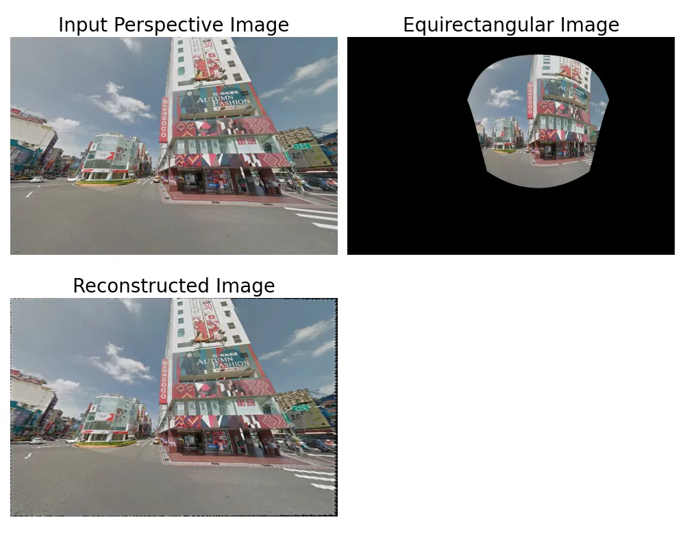
Perspective to Equirectangular

Procedure for mapping from Perspective to Equirectangular projection.
The procedure for mapping from perspective to equirectangular (illustrated above) is as follows
- Generate a uniform grid of points that represent the equirectangular image. This can be done by generating a grid of points between and mapping them top the spherical coordinates.
- Convert the uniform spherical coordinates to Cartesian (world) coordinates using the
spherical_to_cartesianfunction. - Convert the world coordinates to camera coordinates using the
world_to_camerafunction and the camera matrix and the extrinsic matrix . - Project the camera coordinates to the image plane and normalize the x, y coordinates.
- Mask out the degenerate points that are "behind" the camera and outside the image plane. Note that since we sampled uniformly from the sphere, there is no guarantee that all those points will be visible in the perspective image.
- Use the
cv2.remapfunction to generate the equirectangular image with the above camera coordinates.
def Perspec2Equirec(img: np.ndarray,
FOV: float,
THETA:float,
PHI:float,
height:int,
width:int) -> np.ndarray:
"""
Args:
img (np.ndarray): Perspective image
FOV (float): Field of view in degrees
THETA (float): Elevation angle in degrees
PHI (float): Azimuthal angle in degrees
height (int): Height of the output equirectangular image
width (int): Width of the output equirectangular image
Returns:
Equirectangular image (np.ndarray)
"""
# Convert the angles to radians
FOV = np.deg2rad(FOV)
THETA = np.deg2rad(THETA)
PHI = np.deg2rad(PHI)
img_height, img_width = img.shape[:2]
K = get_camera_matrix(FOV, img_width, img_height)
R = get_extrinsic_matrix(THETA, PHI)
# Invert the extrinsic matrix (its orthogonal)
R = R.T
# Generate the grid points for the equirectangular image
u, v = np.meshgrid(np.linspace(0,1,width), np.linspace(0,1,height))
# Map the above equirect coordinates to spherical coordinates
theta = 2 * np.pi * (u - 0.5)
phi = np.pi * (v - 0.5)
# The above block is equivalent to
# theta, phi = np.meshgrid(np.linspace(-np.pi, np.pi, width), np.linspace(-np.pi/2, np.pi/2, height))
# Construct the spherical Coordinates
sp_coords = np.stack([np.ones_like(theta), theta, phi], axis=-1)
# Convert the spherical coordinates to cartesian (world) coordinates
coords = spherical_to_cartesian(sp_coords).astype(np.float32)
# Make the world coords homogeneous
coords = np.append(coords, np.ones_like(coords[..., :1]), axis=-1)
# Map the world coordinates to camera coordinates
camera_coords = world_to_camera(coords, K, R)
# Project and x, y coordinates to the image plane and normalize
uv = camera_coords[..., :2] / camera_coords[..., 2:3]
uv = uv.astype(np.float32)
# Mask out the points that are "behind" the camera
mask = camera_coords[..., 2] > 0
mask *= np.where((uv[..., 0] >= 0)&
(uv[...,0] < img_width)&
(uv[...,1] >= 0)&
(uv[...,1] < img_height), True, False)
equirec = cv2.remap(img, uv[..., 0], uv[...,1], cv2.INTER_CUBIC, borderMode=cv2.BORDER_WRAP)
equirec *= mask[..., None]
return equirec

Mapping from Perspective to Equirectangular and back
| [1] | Cubemaps are another popular 360 degree projection format. Google's Equiangular Cubemap (EAC) have become quite popular for efficient and others like GoPro have even adopted this format. For map projections, although Equirectagnular is one of the oldest, due to its high distortion (neither areas nor angles between cruves are preserved), it is seldom used. |
| [2] | A couple of good references for camera model and their history can be found here and here. |